
Custom Cleanroom HVAC System Design for Optimal Air Quality Control
2026-08-26
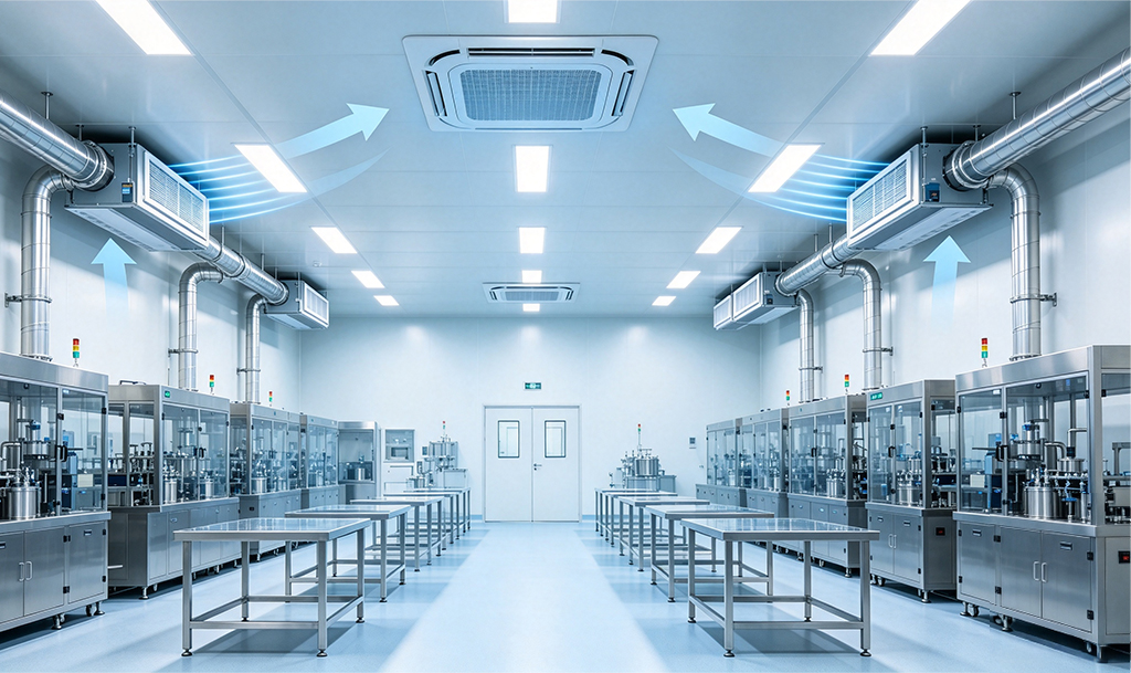
Most cleanroom failures aren’t caused by filters or equipment—they’re caused by HVAC designs that treat air quality as an afterthought. In pharmaceutical and biotech facilities, even a 0.5°C fluctuation or a slight pressure drop can compromise sterility, batch integrity, and regulatory compliance. Custom cleanroom HVAC system design changes that equation. At GENO Pharmatech, we know that optimal air quality control isn’t about adding more filtration—it’s about engineering airflow, temperature, humidity, and pressurization to work as one system. This post unpacks what truly goes into a tailored cleanroom HVAC design, from load calculations to redundancy planning, and why off-the-shelf solutions often miss the mark.
Mapping Airflow to Cleanroom Classification Needs
Cleanroom classifications set hard limits on particle counts per cubic meter, and those limits dictate how air must move. In ISO 5 or stricter environments, unidirectional airflow is rarely optional—typically a steady 0.3 to 0.5 m/s velocity sweeps particles away from the critical zone. But pushing more air doesn't automatically mean a higher class; uneven velocity or small vortices can resuspend particles and create contamination pockets that sampling might miss.
For ISO 7 and ISO 8 spaces, the design logic shifts from displacement to dilution. Air changes per hour become the main lever, often ranging from 20 to 60 ACH depending on internal activity and equipment load. The mapping step is about estimating actual particle generation, not just reading a table. A heavily automated ISO 7 area might need 60 ACH to stay within limits, while a low-occupancy manual workstation could hold at 25 ACH.
Pressure differentials and airflow direction also need to be mapped across classification boundaries, keeping lower-grade air from bleeding into high-grade zones. Beyond static settings, recovery testing matters—how fast a room returns to its target class after a disturbance. In practice, mapping airflow to classification needs is iterative: start from the particle limit, choose a flow pattern and ACH, then verify with real measurements and adjust for the room's actual behavior.
Layering Filtration for Particles and Molecular Contaminants
A single filter cannot handle both fine dust and gaseous contaminants well. Particulate matter gets trapped by fibrous media, while molecules such as ozone, formaldehyde, or hydrogen sulfide slip right through unless a sorbent or reactive layer is present. So the most reliable systems stack several stages, each assigned a narrow job. The first stage is usually a low-cost prefilter that catches hair, fibres, and coarse dust before they can clog the more expensive media behind it.
After the prefilter, a high-efficiency layer—often pleated or bag-style—removes fine particles through interception, impaction, and diffusion. Only then does the air meet a molecular filtration layer. Activated carbon is common for general VOC control, but impregnated carbons or specialty chemisorbents are needed for acid gases, bases, or specific organic compounds. This order keeps dust off the sorbent, preserving its adsorption capacity.
Good layering is not just about stacking media; it is about matching each layer's resistance and dust-holding capacity to the overall airflow. Too many high-efficiency stages can create an unacceptable pressure drop, raising fan energy and shortening filter life. In practice, facilities tune the sequence—say, a MERV 8 prefilter, a MERV 14 final particulate filter, and a carbon bed—to hit the required air cleanliness without choking the system.
Designing Pressure Cascades That Keep Contaminants Out
Pressure cascades work on a simple principle: air always moves from higher to lower pressure. In a well-designed facility, that means the cleanest zones sit at the highest pressure, while progressively dirtier or more hazardous areas are held at lower pressures. When a door opens or a small leak occurs, the outward flow from the clean side physically blocks unfiltered air from pushing in. The trick is setting the right differential—too small and you lose the barrier, too large and you create drafts that disrupt sensitive processes or make doors hard to operate.
A common mistake is treating static pressure readings as the whole story. Real containment depends on dynamic behavior: how pressure shifts when an anteroom door swings open, when an exhaust fan cycles, or when someone walks past a critical opening. That's why many designs now include active monitoring tied to the building automation system, with alarms that trigger if a cascade drops below its target. But alarms alone won't save you—the physical layout must establish a logical gradient first. Air should flow from clean corridors into workrooms, then into waste or decontamination spaces, never the reverse.
One underappreciated detail is the role of return air paths and transfer grilles. If a room is pressurized but has no low-resistance route for air to leave, the cascade collapses the moment the supply fan modulates. Designers often fixate on supply and exhaust volumes while forgetting that the pressure relationship only holds if the air has somewhere to go. Placing transfer grilles with proper dampers, sizing door undercuts, and accounting for filter loading over time all matter more than the nominal setpoint on a drawing. Getting the cascade right means thinking about the entire airflow network, not just the numbers on a control screen.
Holding Temperature and Humidity Within Tight Process Windows
Maintaining temperature and humidity within tight process windows is not just a matter of setting a thermostat and walking away. In many production environments—from pharmaceutical freeze-drying to semiconductor lithography—even a half-degree drift or a few percentage points of relative humidity can lead to rejected batches, warped substrates, or compromised coatings. The real challenge lies in the fact that these two variables interact in non-linear ways: cooling air can inadvertently raise its relative humidity, while a humidity spike can trigger localized condensation that undermines temperature uniformity. Operators quickly learn that you cannot treat them as independent dials; they must be managed as a coupled system with continuous feedback.
To hold such tight tolerances, facilities typically deploy a layered control strategy. At the core are high-accuracy sensors—often chilled-mirror hygrometers for humidity and platinum resistance thermometers for temperature—sampling multiple points across the workspace. These feed into a controller that uses model-based or adaptive algorithms, rather than simple on/off hysteresis, to modulate chilled water valves, reheat coils, and desiccant or steam humidifiers. The goal is to anticipate disturbances before they cause a visible error. For instance, when a process door opens or a batch of heat-generating equipment starts up, the system should pre-emptively adjust airflow and moisture injection to keep the environment within a fraction of the specified range. Simply reacting after the fact is usually too slow.
Beyond the hardware, staying inside a narrow window demands rigorous operational discipline. Sensors need calibration against traceable standards more frequently than in looser environments, because even a small offset can push you outside the allowable band. Maintenance teams often schedule filter changes, coil cleaning, and damper actuator checks based on observed drift patterns rather than fixed calendar intervals. It also helps to map the room's air distribution with smoke tests or computational fluid dynamics, then reposition supply diffusers or add local recirculation to eliminate microclimates. Without these ongoing practices, even a well-designed HVAC system will gradually wander, and the process window that once seemed comfortably wide will close in without warning.
Recovering Energy Without Sacrificing Cleanliness
Many facility managers once believed that capturing waste heat meant accepting a drop in hygiene standards. That assumption no longer holds. Modern heat exchangers pull thermal energy from exhaust air or wastewater without letting contaminants cross into the fresh supply. The result is a system that pays back its cost through lower utility bills while keeping indoor air and surfaces as clean as before.
Take a commercial laundry as an example. Hot wastewater used to go straight down the drain, taking valuable BTUs with it. Now a plate-and-frame exchanger transfers that heat to incoming cold water, raising its temperature by thirty degrees or more. The two streams never mix, so lint, detergent residue, and pathogens stay out of the clean water line. Operators get hot water for the next wash cycle without any extra fuel burn or hygiene risk.
The same principle applies to kitchens, swimming pools, and even industrial drying rooms. By choosing closed-loop recovery units with smooth, self-draining surfaces and easy access for inspection, managers avoid the hidden cost of biofilm buildup. Energy recovery and cleanliness are no longer competing goals; they reinforce each other when the equipment is designed with both in mind.
Validating Real-World Performance Beyond Standard Tests
Synthetic benchmarks can only tell you so much about how a product actually behaves when it is pushed off the test bench and into daily life. The numbers look tidy on a spec sheet, yet they rarely capture the slow degradation of battery life over six months, the subtle lag that appears when switching between a dozen open apps, or the way a camera hunts for focus under mixed indoor lighting. Real-world validation means putting a device in the hands of people who treat it carelessly — shoving it into pockets with keys, streaming video on patchy cellular networks, and running navigation in direct summer heat — then measuring how well it holds up without the controlled conditions of a lab.
This approach often reveals contradictions that standard tests miss. A laptop might ace a graphics benchmark but thermal-throttle badly after twenty minutes of rendering, turning smooth frame rates into a stuttering mess. Wireless earbuds can show strong latency numbers on paper, yet constantly drop connection in a crowded subway car. By gathering data from extended use scenarios, temperature logs, and user-reported glitches, we build a picture that reflects genuine reliability rather than peak capability. What matters is not the best-case score from a fresh unit, but how performance holds steady after weeks of accumulated background processes, file fragmentation, and physical wear.
In the end, validation beyond standard tests is about trust. A device that survives a standardized drop test from three feet may still shatter when it slips out of a back pocket onto concrete at a slightly different angle. Real-world testing acknowledges randomness and environmental messiness, giving consumers a more honest forecast of what they will experience. This is why we combine structured stress tests with unstructured, long-term field notes — so that when a product earns a recommendation, it is not because it impressed a machine, but because it proved itself in hundreds of unpredictable, everyday moments.
FAQ
The choice hinges on the ISO cleanliness class, the location and intensity of particle generation, and the process sensitivity. Unidirectional flow is essential for ISO 5 or stricter zones where particles must be swept away in a single pass, while non-unidirectional flow suits less critical areas where dilution and mixing are acceptable.
You stage cooling, reheating, and precision humidification with sensors placed close to critical zones. The air handling unit's coil arrangement and drain pan design are specified so moisture never lingers on surfaces, and supply air dew point is kept below the room's lowest expected surface temperature.
Custom duct routing avoids dead legs, abrupt transitions, and inaccessible sections where dust can accumulate. Interior surfaces are specified to be smooth and cleanable, all joints are sealed to prevent leakage, and the layout supports the required pressure cascade without excessive turbulence at diffusers.
A practical custom design usually includes a pre-filter, an intermediate filter, and then HEPA or ULPA terminal filters sized for the target ISO class. The exact combination depends on outdoor air quality, recirculation ratio, and whether the process demands chemical or molecular filtration in addition to particulate control.
Variable speed drives on fans, demand-based airflow reduction during idle periods, and heat recovery from exhaust are common. You can also install filters with lower initial pressure drop and monitor them to replace on pressure differential rather than fixed schedules, reducing fan energy over time.
Pressure differentials maintain the directional airflow that isolates the cleanroom from adjacent areas. Continuous monitoring with alarms is needed because a failed fan, an open door, or a clogged filter can reverse the cascade, allowing contaminants to enter. In pharmaceutical or semiconductor settings, this data also supports regulatory compliance.
The original HVAC design should include spare fan capacity, modular duct connections, and enough ceiling plenum space for additional HEPA or ULPA terminal filters. Control sequences should allow for higher air change rates and tighter pressure differentials, so the room can be upgraded without major structural changes or system replacement.
Conclusion
Achieving the cleanroom classification isn't about installing oversized fan filter units and hoping for the best. It starts by mapping the airflow path against the actual process signatures—where particles are generated, how they drift, and which ISO class each zone must hold. In practice, this means balancing supply and return air so that unidirectional flow is maintained only where product is exposed, while turbulent mixing zones are allowed to do their job without wasting energy. Filtration then gets layered in a deliberate sequence: a pre-filter catches coarse debris, an intermediate filter protects the high-efficiency stage, and a final HEPA or ULPA bank polishes the air. Where airborne molecular contamination threatens yields, chemical filters or adsorptive media sit upstream of the terminal filters, sized for the specific acids, bases, or organics present in the facility. Pressure cascades are tuned as a single system, not a collection of setpoints—each door opening or exhaust change shifts the balance, so the controls must react quickly to keep air always moving from cleaner to less clean spaces.
Temperature and humidity control is equally unforgiving because many processes drift out of specification with a swing of only one degree or a few percent relative humidity. This demands coil selections and dehumidification strategies that can hold tight bands without short-cycling or fighting the cleanroom's own heat loads. Energy recovery is woven into the design only after the cleanliness requirements are locked: runaround coils, sensible wheels, or heat pipes recover heat without allowing cross-contamination, and the payback is calculated against the cost of treating makeup air. Finally, the real proof is not a certificate from a standard test but how the room behaves on a bad day—when a pass-through is left open, a filter is loaded unevenly, or an exhaust fan ramps down. That is why validation extends to challenge testing under dynamic conditions, particle counts during simulated operations, and recovery time after a deliberate upset. A custom system earns its name only when these layers work together without constant manual intervention.
Contact Us
Contact Person: Amy Yang
Email: [email protected]
Tel/WhatsApp: 008619330882686
Website: https://www.genopharmatech.com/