
Fourth Generation Hydraulic Cement Mold Recommendations for Modern Construction Projects
2026-10-02
Ask any project manager about the biggest bottlenecks in modern construction, and formwork will likely come up. The fourth generation of hydraulic cement molds is changing that conversation—reducing setup time, improving dimensional accuracy, and handling complex shapes with far less manual labor. Yet with more options on the market than ever, knowing which features actually matter can be tough. This guide breaks down the key recommendations for selecting and using these advanced molds on today’s demanding projects. Along the way, we’ll highlight practical insights from LugongMachinery, a name worth watching in this space.
Assessing Fourth-Generation Hydraulic Advancements for Site Conditions
Matching a fourth-generation hydraulic system to a specific site starts with more than just pressure and flow ratings. The local soil profile, ambient temperature swings, and even the operator's duty cycle shape how the system behaves once it leaves the test bench. On a compact urban infill job, for instance, the same pump-and-valve package that performs well on open terrain may struggle with heat rejection when surrounded by tall structures that block airflow. Field assessments therefore need to capture not only the peak demand numbers but also the softer variables: how long the machine idles between cycles, whether the ground is abrasive enough to accelerate wear on cylinder seals, and whether overnight temperatures will thicken the hydraulic fluid beyond the comfort zone of the control electronics.
A practical way to evaluate these site-specific factors is to log real-time data from the machine's CAN bus over several representative shifts, then compare that against the manufacturer's steady-state curves. The differences often reveal hidden inefficiencies, such as a pressure-compensated pump spending most of its time near deadhead because the operator feathers the joystick instead of working in full-stroke detent. Adjustments like tuning the load-sensing margin, switching to a wider-temperature-range fluid, or reprogramming the electrohydraulic valve response can then be made with confidence. Ultimately, the goal is not to force the site to fit the system, but to let the system adapt to how the site actually works.
Choosing Mold Profiles That Minimize Cement Waste
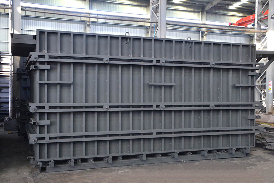
The edges and corners of a mold do more than shape the final product—they decide how much cement ends up stuck in the form or scraped off after demolding. Sharp internal angles tend to trap wet paste, especially in mixes with fine aggregates or higher viscosity. By switching to profiles with larger radii at intersections and a slight taper on vertical walls, the cement releases more cleanly, leaving less residue behind.
Rounded or chamfered lips along the top edge also help when excess material is struck off. A crisp square edge encourages paste to cling to the rim, while a gentle bevel lets the screed glide through and pushes surplus back into the pour rather than onto the floor. Even a small change—such as replacing a 90-degree bottom corner with a 5 mm radius—can reduce the amount of hardened cement that has to be chipped away before the mold is reused.
The goal is to match the profile to the mix and the release system. Some plants find that a slightly deeper draft angle on tall sides prevents micro-tearing at the surface, which in turn lowers the need for patching after demolding. Over dozens of cycles, these adjustments mean less material thrown away, fewer cleaning hours, and a mold that keeps its geometry longer.
Hydraulic Pressure Settings for Thin-Wall and Complex Forms
Start thin-wall runs with hydraulic injection pressure around 70–80% of machine maximum, then creep upward only until short shots vanish. Because thin sections lose heat fast, use velocity-controlled fill and keep pressure from becoming the limiting factor during the first 70% of stroke. After the cavity is visually full, switch to hold pressure early—waiting too long at high pressure often forces flash along vent lines even when the clamp stays closed.
For complex forms with ribs, bosses, and sudden wall changes, avoid a single flat hold setting. Set the first hold stage to roughly 50–60% of peak injection pressure for two to three seconds, then drop to 30–40% for the remainder of cooling. This stepped curve lets the gate seal without packing the thicker areas too aggressively, which reduces sink marks and keeps flat sections from bowing.
Back pressure rarely needs to exceed 5–10 bar hydraulic on these geometries; higher settings add shear heat and can degrade melt consistency in thin sections. If the machine allows segment-specific hold pressure, dial back pressure near the last-filled corners by 10–15% compared to the gate area so those regions do not overpack. Check clamp force only after the part stops flashing—many thin-wall defects look like pressure problems but are actually insufficient clamp tonnage at the higher injection pressures required.
Coatings That Keep Fourth-Gen Molds Releasing Cleanly
Fourth-generation molds push the limits of part complexity and dimensional accuracy, which also makes clean release more demanding. Thin-wall sections, deep ribs, and textured surfaces all create natural grip points where a part can hang up or tear. A well-chosen mold coating changes that dynamic by lowering the surface energy at the tool face. PVD-applied layers such as chromium nitride or diamond-like carbon give the steel a slick, non-wetting character that lets polymers slide off without dragging, even at elevated mold temperatures.
These coatings do more than reduce sticking. Their dense, hard surfaces resist the micro-scratches and build-up that gradually roughen a mold and invite adhesion. Shops often find they can cut back or eliminate external release agents, which keeps the cavity cleaner and the part finish more consistent. Less residue also means fewer interruptions for wiping down cores and slides, so production runs stay longer and more stable.
The right coating depends on the resin, fillers, and processing conditions. Glass-filled or abrasive materials call for multi-layer nanocomposite coatings that combine toughness with low friction, while unfilled grades may release well with a thinner ceramic topcoat. Matching the coating to the mold's most challenging areas—ejector pins, lifters, and sharp edges—helps ensure every cycle ends with a clean break rather than a sticky surprise.
Modular Design Strategies for Rapid Project Turnarounds
When timelines shrink, breaking a project into self-contained modules changes the entire workflow. Each module gets defined boundaries, a clear interface, and its own delivery milestone. That isolation means a designer can fully wrap up the navigation component while the content team is still refining copy for the hero section, with no one stepping on anyone else's work. Instead of one massive handoff at the end, you end up with a series of smaller, reviewable chunks that can be approved and integrated as soon as they're ready.
This approach also turns your previous work into a library of starting points. Once a button style, card layout, or form pattern is built as a standalone module, pulling it into a new project takes minutes rather than hours. Teams can run user tests on individual pieces early, fix issues without unraveling the whole design, and keep the overall project moving even when a specific part hits an unexpected delay. The result is a tighter feedback loop and a much faster path from first sketch to final launch.
Inspection Routines That Catch Wear Before It Affects Tolerances
Wear rarely announces itself with a loud failure. It begins as a subtle shift in surface finish, a faint ridge on a bearing race, or a barely audible change in spindle tone. Shops that rely only on scheduled tool changes or post-process measurements often discover these signs after a part has already drifted out of spec. The most effective routines treat inspection as a continuous thread woven through production, not a checkpoint at the end.
One practical approach is to pair quick manual checks with a few well-chosen automated measurements. A machinist might run a fingernail across a critical seal land while the next part is loading, looking for the telltale edge that indicates a worn insert. At the same time, an in-process probe can capture bore diameter or shoulder position every few cycles. When those two signals start to diverge from baseline, the team knows wear is accelerating before the tolerance band tightens.
It also helps to keep a simple wear log rather than a complex database. A note like "slight taper on OD after 400 parts, adjusted offset +0.003 mm" tells the next shift more than any dashboard. Over time, these notes reveal patterns: certain tools wear predictably after a certain number of cycles, certain materials cause faster flank wear, certain operators catch issues earlier because they listen to the machine differently. That accumulated intuition, combined with a few regular measurements, turns inspection from a safety net into a way of seeing wear before it ever reaches the print.
FAQ
The biggest jump is in how pressure distributes across the face plate. Fourth gen units use staggered internal channels that reduce dead spots, so you get more consistent density without manually shifting the pour. They also tend to have quicker release collars and fewer external grease points, which matters when crews are moving between pours on a tight schedule.
Curtain wall panels, precast stair cores, and blast-resistant facade elements see the clearest gains. These components often have tight dimensional tolerances and embedded connection plates, and the newer molds hold alignment under repeated high-frequency vibration much longer than earlier designs.
Look beyond the rated pressure. Check the wear strips near the side rails, ask for a cycle count from the previous owner if it is a refurbished unit, and run a short test pour with your actual aggregate blend. Small differences in aggregate shape can expose weak spots in channel flow that a factory demo with fine sand will hide.
In most cases, yes. Because the cavity fills more uniformly, you can often lower the water content slightly or reduce the vibration time. But you need to verify the mix's thixotropy first. A mix that was borderline with a third gen mold may flash set in a fourth gen unit if the cement is fresh and the ambient temperature is high.
Daily removal of cement dust from the guide pins, weekly checks of the pressure relief valve setting, and replacing the wiper seals before they become brittle are non-negotiable. Also, never store the mold under direct sunlight with the face plate clamped tight; thermal expansion will bow the plate enough to throw off panel flatness over time.
Retrofitting is possible for the hydraulic manifold and quick-connect fittings, but the core advantage of fourth gen molds lies in the internal channel geometry and plate stiffness. Those cannot be retrofitted without cutting the mold body, which usually voids the original pressure rating and costs more than a new mid-size unit.
Teams often keep the same release agent and cleanup cycle, then wonder why the surface develops micro-pinholes. Fourth gen molds seal tighter, so old release agents build up faster in the corners and the higher compaction pushes air out differently. Switching to a low-viscosity, water-based release agent and blowing out the vents after each pour usually solves it.
Conclusion
Modern construction sites demand forming systems that keep pace with faster schedules and tighter tolerances, and fourth-generation hydraulic cement molds answer that call by pairing smarter pressure control with material-conscious design. Assessing site conditions first means reading slump, ambient temperature, and aggregate consistency before locking in hydraulic parameters, because even a small shift in mix flow can turn a clean pour into a honeycombed wall. From there, choosing mold profiles with draft angles and rounded internal corners does more than ease stripping—it directly cuts cement waste by reducing over-pour pockets and the need for post-cure grinding. For thin-wall and complex forms, hydraulic pressure settings should be dialed back at sharp changes in section and then ramped gradually, allowing the paste to migrate without forcing aggregate segregation or blowouts at weak joints.
Equally important is what happens at the mold face and in the maintenance bay. Fourth-gen molds work best with sacrificial or semi-permanent coatings that bond to the release layer rather than the concrete, so stripping becomes predictable and surface defects drop sharply without resorting to heavy diesel sprays that stain architectural finishes. Modular design strategies take that further: using standardized side rails, interchangeable end plates, and quick-connect hydraulic manifolds lets crews reconfigure a mold set between footings, columns, and shear walls in hours instead of days, which is where rapid project turnarounds are won. Finally, inspection routines should be built around wear indicators like edge rounding, plate thinning, and seal compression, with a simple go/no-go gauge kept at the form yard. Catching these issues early preserves dimensional tolerances and prevents the kind of mid-pour hydraulic drift that quietly turns a good mold into a liability.
Contact Us
Contact Person: Zhang Zhenlai
Email: [email protected]
Tel/WhatsApp: 8618563210000
Website: https://en.lugongmachinery.com/