
Industrial Stainless Steel Ball Valves Key Factors for Reliable Flow Control
2026-11-16
Flow control in demanding industrial systems often hinges on one component: the stainless steel ball valve. Yet material choice alone does not guarantee dependable shutoff or long service life. Pressure drops, thermal cycling, seat material, and maintenance access all shape whether a valve performs or becomes a hidden bottleneck. This post examines the factors that actually determine reliable flow control and highlights how UPTAI addresses them without the usual trade-offs.
Material Choices That Survive Corrosive Service
Process engineers quickly learn that the initial cost of a material rarely tells the whole story. A stainless steel that performs beautifully in a clean water loop can turn brittle within months when exposed to chlorides, while a seemingly outdated alloy might outlast everything else on the flange schedule. The real skill lies in matching not just the chemical composition but the expected temperature swings, flow velocity, and the presence of trace contaminants that often go unmentioned in the datasheet.
Duplex stainless steels earn their place in offshore topsides and desalination plants because they balance chloride stress corrosion cracking resistance with a price tag that doesn't sink a project budget. Yet pushing them past roughly 300 degrees Celsius invites embrittlement, a reminder that every alloy carries a hidden expiration date tied to service conditions. Nickel-based alloys like Inconel 625 or Hastelloy C276 step in where acids and oxidizers team up, but using them everywhere would be engineering overkill and financially reckless.
The survivors of corrosive service tend to share a common trait: someone looked beyond the generic corrosion table and asked what actually fails in the field. Weld zones, crevices under gaskets, stagnant pockets during shutdowns, and even galvanic couples with nearby carbon steel can undo a material choice that looked flawless on paper. A material that survives is rarely the most expensive option; it is the one whose limitations were understood before the first flange was torqued.
How Seat and Seal Design Prevents Costly Leaks
Leaks rarely announce themselves with a dramatic failure. More often, fluid finds a narrow path between two surfaces that looked flat to the naked eye but were never truly mated under load. A well-designed seat does not rely on brute clamping force to close those paths. Instead, it shapes the contact band so that surface pressure stays concentrated where sealing must happen, while the surrounding geometry gives the seal room to flex without pinching. That balance matters because over-compression is just as damaging as under-compression: it can crack hard seat materials or permanently deform softer ones.
Material choice alone cannot rescue a poorly shaped seat. The best seat and seal pairs are designed to work as a system, with one surface allowed to wear slowly while the other remains stable. A slight taper or radius on the sealing edge can direct wear into a predictable, continuous line rather than scattered flat patches. In thermal cycling, differential expansion tries to open gaps where the seat meets the body. Designs that include a controlled interference fit or a resilient backing element absorb that movement before it becomes a leak path, especially in services where temperatures swing by hundreds of degrees.
The difference between a nuisance leak and a reliable seal often shows up in the details that are easy to overlook. Anti-extrusion clearances prevent soft seal materials from squeezing into gaps under high pressure, while surface finish controls how well the two faces bed in during early cycles. Some designs add a self-energizing feature: process pressure acts on a lip or angled face to increase contact force only when the system needs it. That kind of passive response keeps the seal tight during startups, shutdowns, and pressure spikes without relying on constant manual adjustment or over-torqued fasteners.
Matching Pressure and Temperature Ratings to Real Conditions
Catalog pressure and temperature ratings usually come from steady-state laboratory tests, but real systems rarely hold still long enough for those numbers to apply directly. A header sized for 150 psi at 73°F can see very different stresses when a steam tracer raises the jacket temperature or a pump kicks on and sends a brief surge through the line. Matching ratings to real conditions starts with identifying the highest pressure and temperature pair the system will actually experience, including startup, shutdown, and upset cases, not just normal running conditions.
It also pays to look at the whole pressure-temperature curve instead of a single published number. Many thermoplastics lose allowable pressure quickly as temperature climbs, and even in metal systems the gaskets, seals, and valve seats often weaken before the pipe itself does. When a process operates near the upper end of that curve, the published limit should be treated as a design ceiling rather than a comfortable margin.
Transient loads can quietly eat away at the remaining safety factor. Water hammer, thermal expansion, and regulator chatter may create short pressure peaks that never appear on a standard gauge, so a component that just meets the steady-state rating can already be undersized for real-world conditions. Leaving some distance below the rated values is usually far less expensive than replacing a cracked fitting or a blown gasket after the fact.
End Connections and Installation Pitfalls Worth Avoiding
A lot of field failures trace back to the same small mistakes: over-tightened compression nuts, burrs left on cut tube ends, or sealants applied where the fitting already has a dry-seal thread. Before you touch a wrench, deburr the tube and check the flare or ferrule for scratches. If the seat is damaged, no amount of torque will make it seal properly.
Another common trap is mixing materials without thinking about galvanic corrosion. Stainless fittings on copper tube can work fine in dry systems, but add moisture or salt air and the joint becomes a battery. Use dielectric unions or match the materials wherever possible. Also watch the thread type: NPT, BSP, and metric fittings look similar but will cross-thread and destroy themselves if forced.
Finally, leave room for maintenance. A valve or filter buried against a wall with no wrench clearance will cost hours later. Install unions or flanges at equipment connections, keep the thread engagement within the manufacturer’s range, and label the direction of flow before the system gets buried in insulation. A little extra care at the ends saves the whole run.
Certifications That Matter Beyond the Data Sheet
A data sheet can list impressive specifications, but a certification is where those claims meet repeated scrutiny. Real weight sits with marks that require unannounced factory inspections, periodic retesting, and traceability of raw materials. That ongoing accountability often reveals more about long-term reliability than any single performance curve printed on page one.
What separates a meaningful certification from a paper badge is the depth behind it. Look for listings that reference specific standards, test conditions, and rated environments rather than broad compliance statements. A credible mark usually means the product was pushed past nominal limits, checked for failure modes, and built with components that can be audited back to their source.
When comparing options, treat certifications as evidence of engineering discipline rather than decoration. Ask which organization issued the mark, what follow-up testing is required, and whether the certification covers the exact configuration you are buying. Products that carry this kind of documentation tend to age better in the field, often because the manufacturer had to design for consistency instead of a one-time pass.
Simple Maintenance Habits That Extend Valve Life
Most valve failures don't happen overnight. They creep in through small, overlooked habits. A quarter-turn too far, a forgotten drip, or a filter left unchanged for months can quietly shorten the life of even the best-built valve. The good news is that a few simple routines can make a noticeable difference. Start by getting familiar with how each valve feels when it opens and closes. A sudden change in resistance often signals debris, corrosion, or a worn stem seal long before a visible leak appears.
Cleanliness at the point of use matters more than people expect. Wiping down the stem and around the packing gland after every shift prevents grit from working its way into the threads. When you operate the valve, do it with a steady hand -- avoid slamming it shut or forcing it past its stop. If the system allows, cycle valves that normally stay in one position once a month. That small motion redistributes lubricant and helps prevent the seat from sticking.
Finally, keep a simple log. Note any leak, unusual noise, stiff operation, or temperature change. You don't need complicated software -- a notebook by the line works fine. Over time, that record will show you which valves need attention before they become an emergency. Replacing a packing set or a worn O-ring during planned downtime is far cheaper than shutting down an entire process at the worst possible moment.
FAQ
316 stainless steel resists pitting and crevice corrosion in wet or chloride-exposed environments, while 304 works well in less aggressive service. Choosing the right grade prevents wall thinning, seal face damage, and premature replacement.
The rating tells you the maximum safe pressure at a reference temperature. At elevated temperatures, metal strength declines, so the actual working pressure must be derated. Ignoring this can distort the body, overload the seats, and lead to stem leakage.
Soft seats made from PTFE or reinforced PTFE give tight shutoff at moderate temperatures, while metal seats tolerate abrasive slurries, high heat, and frequent cycling but may not seal as tightly. The seat choice should match the dirtiest and hottest upset condition, not just normal service.
Thermal cycling and repeated operation cause packing to lose compression. Live-loaded packing uses springs to maintain constant gland pressure, which helps prevent stem leaks as the packing wears. A blowout-proof stem is also critical for safety in high-pressure lines.
Misaligned pipe flanges can transfer stress to the valve body, distort the seats, and cause binding. Using the wrong thread sealant, over-torquing a connection, or welding without removing soft parts can also damage seals before startup.
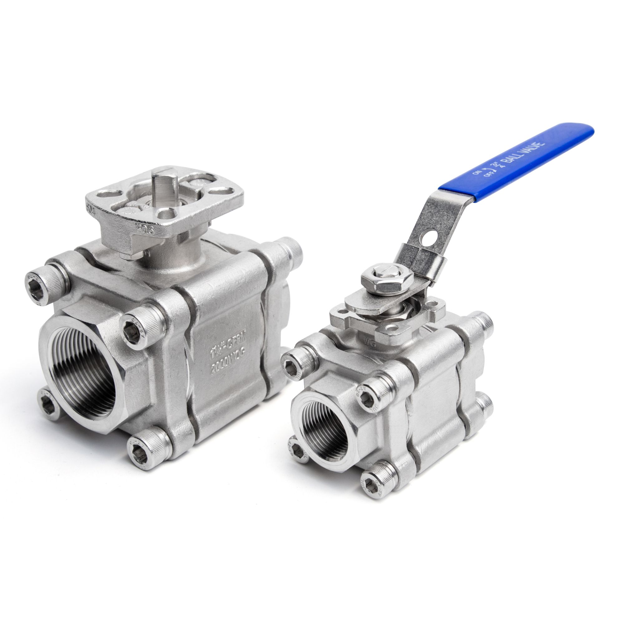
A three-piece design allows the center section to swing out after loosening bolts, so the ball, seats, and stem can be serviced without cutting the pipe. This is especially useful in sanitary or high-cycle applications where downtime is expensive.
Process residue, scale, or dried product can build up around the ball and stem. If a valve is never cycled, buildup hardens and the operating torque increases. Periodic partial stroking, flushing after batch runs, and using a cavity filler in dirty service can keep movement free.
Standard ball valves are meant for on-off service. Using them in a partially open position for throttling exposes the seats and ball edges to high-velocity flow, causing erosion and vibration. If continuous modulation is needed, a characterized ball or a dedicated control valve is generally a better option.
Conclusion
Reliable flow control with stainless steel ball valves rarely comes down to a single design feature. In corrosive lines, the alloy grade matters as much as the layout of the valve itself; 316 stainless works for many chemical exposures, but chloride-heavy or acid service can demand upgrades like duplex, alloy 20, or Hastelloy. Seat and seal selection is equally decisive because a well-chosen ball and stem seal stops the small leaks that erode uptime and safety. Matching the valve's pressure and temperature envelope to actual operating swings prevents the quiet failures that happen when ratings look acceptable on paper but fall short during thermal cycling or pressure spikes.
Field experience also points to installation and maintenance habits that separate dependable valves from frequent rework. Proper end connection alignment, clean thread engagement, and correct torque reduce stress on the body and keep the seat geometry intact. Certifications such as API 607 fire-safe testing or ISO 15848 fugitive emission approval carry weight only when the valve is installed and serviced as intended. A practical routine of cycling valves periodically, checking gland tightness, and inspecting seats before they harden or score can extend service life far beyond expectations, keeping flow control predictable without overcomplicating the maintenance plan.
Contact Us
Contact Person: Adonis
Email: [email protected]
Tel/WhatsApp: 8615858822657
Website: https://www.uptaivalve.com