
Professional Robotic Bending Techniques for Precise Sheet Metal Fabrication
2026-10-27
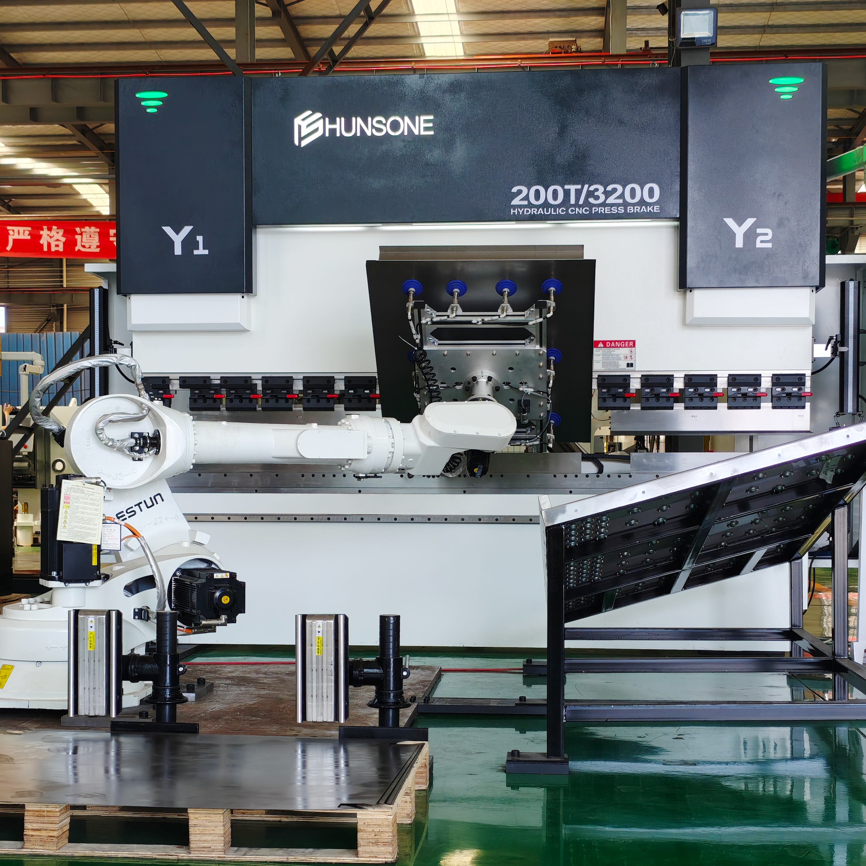
Robotic bending has reshaped the landscape of sheet metal fabrication, turning a traditionally skill-heavy process into a repeatable science. Yet not every automated setup delivers the tight tolerances and crisp angles that precision work demands. At HUNSONE, we see firsthand how the right combination of tooling, software, and bend sequencing separates acceptable parts from flawless ones. This post breaks down professional robotic bending techniques that help fabricators minimize springback, control material flow, and maintain consistency across high-mix production runs—without relying on guesswork or endless trial bends.
Bend Allowance Without the Trial-and-Error
Sheet metal shops often lean on bend allowance tables built from years of shop-floor experiments. But when a new material, thickness, or tooling setup appears, those tables fall short, and the old trial-and-error method eats up time and scrap. Instead of guessing and bending sample after sample, you can calculate the allowance directly from the geometry of the bend and the material's response to deformation. The neutral axis—the layer inside the sheet that neither stretches nor compresses—sits at a predictable fraction of the thickness, usually between 0.3 and 0.5 depending on the inside radius and material hardness. Once you nail down that k-factor for your specific setup, the bend allowance becomes a simple formula: the arc length of that neutral axis through the bend angle.
The practical advantage comes from treating the k-factor as a property of the bending process, not a mystery to rediscover every time. For a given punch radius, die opening, and material grade, the k-factor stays remarkably consistent. You can find it once with a single test bend—measure the flat length before bending, bend to a known angle, then measure the outside dimensions and back-calculate the actual arc length. With that value in hand, every future bend of the same material and tooling combination can be computed on paper or in a simple spreadsheet. No more cutting extra blanks, no more dialing in the press brake by feel, and no more pile of bent test pieces headed for the recycling bin.
Even better, this approach scales to complex parts with multiple bends. Instead of adjusting each bend individually, you calculate the entire flat pattern up front, confident that the allowance for each bend matches reality. The result is a cut blank that folds into the finished part within tolerance on the first try, or at worst needs only a tiny adjustment. That shift from trial-and-error to a calculated method doesn't just save material—it frees up the press brake for production work and lets you quote new jobs with tighter margins and shorter lead times.
Tooling Setups That Survive High-Mix Production
High-mix shops often learn the hard way that tooling decisions made for volume production collapse when the part number changes every few hours. The setups that last are the ones that move adjustment off the machine. One contract manufacturer cut average changeover from 38 minutes to 9 by mounting every vise and fixture on the same zero-point base plate and pre-setting all tools offline. The operator just swaps the pre-loaded pallet, scans a QR code to load tool offsets, and starts cutting. No dialing in, no edge finding, no guesswork.
Modularity matters, but it has to be bounded. Shops that survive high mix don't try to standardize everything—they define a few repeatable interfaces and let the rest vary. For example, using only two locating pin diameters and three fixture plate sizes across all machines still allows dozens of part families, but eliminates most misloads. Color coding and physical poka-yoke features do more than any software warning. One shop went further by printing lightweight fixture pallets from carbon-fiber-filled nylon, so a single operator can lift and swap an entire setup without a hoist.
Finally, tooling setups need feedback loops. In high-mix work, a setup that runs fine this week may drift next month because a locating bushing wears or a torque wrench falls out of calibration. Tracking repeatability of zero-point clamping units and logging every changeover delay reveals patterns. A team analyzing its own downtime found that 80% of setup errors were tied to manual entry of tool length offsets. They switched to automatic offset transfer from the presetter and added a quick second-person verification step. Offset errors went to zero, and the setup stayed viable even as part variety doubled.
Offline Programming: Where the Real Accuracy Starts
Most people assume robot accuracy comes from the hardware—better encoders, tighter gearboxes, stiffer castings. But step onto a shop floor and you'll see the real source of error isn't the arm, it's the programmer hunched over a teach pendant, nudging points by eye. Offline programming flips that equation. By building the entire cell in a virtual environment first, you stop approximating positions and start defining them. The robot's path is generated from CAD geometry, not from squinting at a laser dot on a weld seam.
This shift matters because real accuracy often fails at the boundary between intention and execution. When you jog a robot to a point, you introduce human variability—slightly off angle, a touch too far, a nudge that felt right but wasn't. Offline programming removes that layer of guesswork. The software calculates reach, joint limits, and collision zones before the robot ever moves. You see exactly where the tool center point will be, down to fractions of a millimeter, before you cut a single piece of metal.
The result is a kind of accuracy that isn't just about repeatability—it's about translating a design into motion without losing fidelity. That's why high-mix shops and aerospace fabricators lean on offline tools: the first part off the machine is already closer to the print. Not because the robot got better, but because the programming stopped being the weak link.
Springback Correction Without Manual Adjustments
Traditional springback compensation often relies on iterative manual tweaks to the tool geometry, which is time-consuming and prone to inconsistency. A more direct path is to embed the correction logic directly into the simulation-to-production workflow. Instead of hand-adjusting die surfaces after each trial, the system can use the measured deviation between the simulated and target part shapes to automatically derive a new tool face. This closes the loop without any operator intervention, letting the software handle the geometric inversion that compensates for elastic recovery.
The key is to treat springback not as a defect to be chased but as a predictable response that can be inverted. By running a single forming simulation with the nominal tool, extracting the nodal displacement field, and then applying the inverse of that field to the tool mesh, you get a compensated geometry in one pass. No manual smoothing or guesswork is needed because the correction comes straight from the physics of the process. This approach also keeps the correction stable across different materials and thicknesses, since the compensation is recalculated for each specific case rather than relying on a generic rule of thumb.
What makes this truly hands-off is that the correction can be integrated into the existing CAD and CAE pipeline. The tool designer simply approves the automatically generated surface, or the system can push the updated geometry directly to CAM. There is no need to export point clouds, rebuild surfaces, or manually tweak control points. The result is a consistent, repeatable correction that removes the bottleneck of human adjustment and lets the digital twin drive the tooling design from start to finish.
Live Feedback Loops That Keep Tolerances Tight
Traditional machining relies on predetermined settings that assume stable conditions, but real production floors are anything but static. Material hardness varies, tools wear down, and ambient temperature shifts can cause metal to expand or contract by microns. Live feedback loops address this by closing the gap between what the machine intends to do and what it actually does. A sensor embedded near the cutting zone measures displacement, force, or thermal drift in real time, and the controller adjusts feed rate, spindle speed, or tool offset before the error grows beyond the allowed tolerance band.
Consider a grinding operation where the wheel loses abrasive grains continuously. Without feedback, the operator would need to stop the process, measure the workpiece, and manually compensate—a slow and inconsistent approach. With live feedback, an acoustic emission sensor detects changes in the grinding signature that correlate with wheel dullness. The control system then commands a finer infeed or triggers a dressing cycle at the exact moment it is needed, keeping the dimensional variation within a few microns across hundreds of parts. This level of tightness is nearly impossible to sustain with periodic inspections alone.
The real advantage comes from the loop’s speed and resolution. A feedback system sampling at a kilohertz can catch a thermal expansion spike before it affects the next cut, while a slower manual check might only reveal the drift after a batch of scrap parts has already been produced. Modern digital controls also store historical drift patterns, allowing the loop to predict and pre-compensate for recurring disturbances such as morning warm-up cycles or coolant temperature swings. By turning tolerance control from a reactive chore into a continuous, automatic correction, these loops let manufacturers hold tolerances that were once reserved for climate-controlled laboratories.
Scaling from One-Off Prototypes to Full Runs
Moving from a single hand-built prototype to a production run of hundreds or thousands exposes every shortcut you took during the build. The wiring harness that was “good enough” for one unit now causes an hour of rework per board. The 3D-printed bracket that survived a demo now warps after the third injection-molded batch. Scaling isn't just making more of the same thing; it's redesigning for repeatability while the clock is running.
A practical shift is to document decisions as you make them, not after the prototype works. If a part was chosen because it was in the lab that day, write that down. If a process depended on a particular person's feel, flag it. These annotations become the bridge to a full run, telling suppliers and line workers why something exists and where tolerance can or cannot be relaxed. Without them, you're reverse-engineering your own prototype under deadline pressure.
Finally, treat the first small batch as a learning run, not a final product launch. Run it with the same materials, tools, and people who will handle the full volume. Measure the time each station takes, note where parts get jammed, and record every deviation from the drawing. That data turns a one-off success into a repeatable process, and it often reveals design changes that cost pennies now but save thousands later.
FAQ
Robotic bending eliminates inconsistencies from operator fatigue and hand positioning by relying on servo-driven axes and closed-loop feedback. The robot can hold a part at the exact same angle and speed every cycle, correcting for springback in real time through angle measurement sensors. This repeatability is what allows tolerances within ±0.1 mm on complex multi-bend parts.
Instead of relying on guesswork, a robotic cell uses an angle sensor right after each bend. The control system compares the actual angle to the target and automatically adjusts the robot's path or the press brake ram for the next piece. Some systems also store material-specific springback coefficients, so switching from stainless steel to aluminum doesn't require manual recalibration.
The gripper is not just holding the sheet—it actively follows the bend as it forms. A floating or compliant gripper design lets the part move naturally with the bend radius, preventing distortion. Specialized finger geometries also allow access to tight bend lines without colliding with the die, which is critical for parts with closely spaced flanges.
Yes, but only if the programming and setup are streamlined. Offline programming software lets a technician simulate the entire sequence before touching a physical part, and quick-change gripper systems reduce changeover to a few minutes. For batches under 20 pieces, the key is automatic tool alignment and pre-calculated bend sequences that eliminate trial runs.
Thermal expansion of the robot arm and sheet material can shift dimensions during long runs, so compensation algorithms are necessary. Another major source is inaccurate blank positioning—if the robot picks up a part slightly skewed, every bend inherits that error. Vision systems or mechanical datums on the gripper help correct this before the first bend.
It allows full kinematic simulation of the robot and press brake together, detecting collisions or unreachable positions before production. The software calculates the optimal robot wrist angles and step positions for each bend, then exports exact coordinates. This removes the need for manual teaching, which always introduces small positional errors.
Beyond standard light curtains and interlocks, a precise bending cell needs safe zones around the moving gripper and backgauge. Since the robot and press brake work in coordinated motion, the control system must monitor both speed and torque continuously. Speed-limited teach mode is also important for setup, allowing technicians to be near the cell without full shutdown.
The robot has to access the bend line from angles that would be awkward or impossible for a human operator, so the punch and die must be profiled to avoid interference with the gripper. Additionally, the tooling must support automatic clamping and alignment—any misalignment at the die is amplified across multiple bends, ruining part flatness.
Conclusion
Robotic bending has moved far beyond simple repeatability. The real gains come from treating bend allowance as a calculated value rather than a shop-floor guess. By feeding exact material properties—thickness, grain direction, tensile strength—into the control software, the first part off the machine is often within tolerance, eliminating the scrap and downtime associated with trial-and-error setups. This upfront precision is reinforced by tooling strategies designed for high-mix production: quick-change clamping systems, staged punch and die setups, and collision-checked tool libraries let a single cell switch between part families without losing alignment or requiring constant re-qualification.
Where the process truly locks in accuracy is offline programming. Simulating bend sequences, detecting potential collisions, and pre-compensating for springback in a virtual environment means the robot arrives at the first physical bend with a proven path. Springback correction becomes a data-driven adjustment rather than a manual tweak: the controller references historical bend results for similar materials and adjusts angles automatically. During production, live feedback loops—using angle measurement sensors or load cells—keep tolerances tight even as material batches vary. This same foundation scales cleanly from one-off prototypes to full runs. A prototype's verified program, tooling offsets, and correction data can be reused directly for production, so the jump in volume doesn't mean a jump in setup time or a drop in repeatability.
Contact Us
Contact Person: James Chen
Email: [email protected]
Tel/WhatsApp: 86 13770803946
Website: https://www.hunsone.com/